Section 37: Bituminous Seals has been greatly revamped and expanded in Caltrans' 2010 Standard Specifications. All of the previously existing information seems to have remained the same (albeit in different format) but the biggest change of which is the addition of specifications for Polymer Modified Asphaltic Emulsion Seal Coat. Much of this addition does not affect aggregate suppliers but one thing to notice is that the aggregate screenings are a different gradation and cleanliness value for the Polymer Modified Emulsion Seal Coat than the standard Asphaltic Emulsion Seal Coat.
If you're in the seal coating business I greatly recommend reading over the new version of Section 37. The Caltrans 2010 standard specifications can be found in pdf form at http://www.dot.ca.gov/hq/esc/oe/standards.php and are now for sale in book form on the Caltrans website here.

Friday, December 16, 2011
Hamburg Wheel Test Overview
There have been varying opinions of the Tensile Strength Ratio (TSR) test and how well it really reflects moisture sensitivity. Because of these concerns, Caltrans is currently moving towards the replacement of the TSR test with the Hamburg Wheel Tracking Test which originated in Germany in the mid 1970s. The test examines the susceptibility of the HMA to rutting and moisture damage.
The Hamburg Wheel Tracking Test uses a steel wheel with weight that rolls over the sample in a heated water bath. A designated number of passes are performed on the sample. I'm not sure what number Caltrans will settle on but in the United States, 20,000 passes seems to be used very commonly. The rut depth is measured by the machine periodically, usually every 20, 50, 100 or 200 passes. 20,000 passes can take around 6.5 hours whereas the entire test can take around 3 days. As you know, this is not much better than the TSR test so it doesn't look like we'll be shortening our mix design turn around time in the near future.
Several analytics are examined with the Hamburg Wheel Tracking Test including post-compaction consolidation, creep slope, stripping inflection point, and stripping slope. The chart below illustrates these pretty well:
This type of information can tell us not only at what point in a roads' life it will become moisture sensitive but also how much the moisture will affect the road once it hits that point. Studies have found that there is good correlation between the Hamburg test and field performance but it has also been determined that the test can fail to differentiate between some mixtures. If you are interested in some of the more nitty gritty details there is a great writeup about the test by the Federal Highway Administration here and an evaluation of the Hamburg test for Caltrans by UC Davis here.
 |
| Hamburg Wheel Tracking Device (HWTD) from (Stuart and Youtcheff, 2002). |
Several analytics are examined with the Hamburg Wheel Tracking Test including post-compaction consolidation, creep slope, stripping inflection point, and stripping slope. The chart below illustrates these pretty well:
 |
| APA Samples showing rutting after 8,000 load cycles. *This chart's data is for the Asphalt Pavement Analyzer, not the Hamburg Device but illustrates the terminology well. |
This type of information can tell us not only at what point in a roads' life it will become moisture sensitive but also how much the moisture will affect the road once it hits that point. Studies have found that there is good correlation between the Hamburg test and field performance but it has also been determined that the test can fail to differentiate between some mixtures. If you are interested in some of the more nitty gritty details there is a great writeup about the test by the Federal Highway Administration here and an evaluation of the Hamburg test for Caltrans by UC Davis here.
The Future of Concrete?
I know that this is primarily a asphalt and aggregate resource but I couldn't help being fascinated by this article that talks about the new innovations involving concrete. Some of the new uses involve concrete printing, modified admixtures using less cement, and CNC-generated concrete form work. It's a short article but well worth the read.
http://www.smartplanet.com/blog/astute-architect/concrete-thinking-new-ideas-for-age-old-material/219
http://www.smartplanet.com/blog/astute-architect/concrete-thinking-new-ideas-for-age-old-material/219
Wednesday, December 14, 2011
Changes to Section 26-Aggregate Bases in Caltrans 2010 Standard Specifications
In the new 2010 standard specifications there has been a change to Section 26-Aggregate Bases. The most exciting of which is that there is no longer a provision that only 50% of the aggregate base can be made from recycled materials. It is now allowed to have any combination of broken stone, crushed gravel, natural rough surfaced gravel, sand, and/or processed reclaimed asphalt concrete, PCC, LCB, or CTB.
The other big change is that the Class 3 Aggregate Base is no longer specified in the special provisions on a job by job basis. The specification is now present in the Standard Specifications. It reads as follows:
26-1.02C Class 3 Aggregate Base
The other big change is that the Class 3 Aggregate Base is no longer specified in the special provisions on a job by job basis. The specification is now present in the Standard Specifications. It reads as follows:
26-1.02C Class 3 Aggregate Base
When tested
under California Test 202, aggregate must comply with the grading requirements
for the sieve sizes shown in the following table:
Aggregate Grading
| ||||
Sieve sizes
|
Percentage passing
|
|||
1-1/2 inch maximum
|
3/4 inch maximum
|
|||
Operating range
|
Contract compliance
|
Operating range
|
Contract compliance
|
|
2"
|
100
|
100
|
--
|
--
|
1-1/2"
|
90–100
|
87–100
|
--
|
--
|
1"
|
--
|
--
|
100
|
100
|
3/4"
|
50–90
|
45–95
|
90–100
|
87–100
|
No. 4
|
25–60
|
20–65
|
40–70
|
35–75
|
No. 30
|
10–35
|
6–39
|
12–40
|
7–45
|
No. 200
|
3–15
|
0–19
|
3–15
|
0–19
|
Aggregate must
comply with the quality requirements shown in the following table:
Aggregate Quality
|
|||
Property
|
California Test
|
Operating range
|
Contract compliance
|
Resistance (R-value) (min)
|
301
|
--
|
50
|
Sand equivalent (min)
|
217
|
21
|
18
|
The Caltrans 2010 standard specifications can be found in pdf form at http://www.dot.ca.gov/hq/esc/oe/standards.php and are now for sale in book form on the Caltrans website here.
*Sorry about the tables looking weird...the platform I'm using doesn't seem to like them and gives me some funky formats...
*Sorry about the tables looking weird...the platform I'm using doesn't seem to like them and gives me some funky formats...
Friday, December 9, 2011
Class 3 Permeable Base
The 2010 version of the Caltrans Standard Specifications now includes a Class 3 Permeable Base. This product has been showing up in special provisions for a while but is now incorporated in the standards. The product can be found in section 68-2.02F(4) and states the following:
"The percentage composition by weight of Class 3 permeable material in place must comply with the grading requirements shown in the following table:
Sieve sizes
|
Percentage passing
|
1-1/2"
|
100
|
1"
|
88–100
|
3/4"
|
52–85
|
3/8"
|
15–38
|
No. 4
|
0–16
|
No. 8
|
0–6
|
At least 90 percent by weight of Class 3 permeable material
must be crushed particles as determined by California Test 205."
The 2010 standard specifications can be found in pdf form at http://www.dot.ca.gov/hq/esc/oe/standards.php and are now for sale in book form on the Caltrans website here.
Monday, November 28, 2011
CT 202 Changes-November 2011
You may have already noticed but Caltrans has posted a new version of CT 202-Method of Tests for Sieve Analysis of Fine and Coarse Aggregates as of November. Luckily there isn't much change this time. In fact, the main test method has not changed at all except for some very minor formatting updates. The noticeable changes to the test method are in Appendix A: Sieve Analysis of Aggregate from Extracted Bituminous Mixtures and are as follows:
- You no longer need to use a washing solution containing denatured alcohol. The test method now only requires distilled, deionized, or good-quality tap water as the washing solution.
- The notes about “sudsing” previously in the materials section of the test method are moved from the materials section to the procedure section.
- For samples extracted using CT 382, washing of the entire sample is no longer required. You can now grade the material as if it was a normal sieve analysis (ex. base rock) and only wash the fine aggregate portion.
- When you add the sample to the wash vessel, you no longer need to add exactly 1000mL of washing solution. Now you will add “enough water to cover sample”.
- The test procedure now adds the wetting agent to the wash vessel before shaking. Previously, although the wetting agent was mentioned in the materials section, the wetting agent was not actually mentioned in the test procedure and as a result was not used.
That's all! The new test method can be found on the Caltrans website and here.
Friday, November 11, 2011
AMRL and Caltrans together at last?
The last thing from the CalAPA meeting that I thought was worth mentioning to our quality control readers is that Caltrans is currently moving towards using AASHTO test methods in the future. They plan to require each lab that tests materials for Caltrans jobs to be AASHTO/AMRL certified in the future. This includes the Caltrans laboratories, and will probably make quite a few independent laboratories happy because there has always been grumblings about how it can't be effective for Caltrans to certify its own laboratories. With AMRL, the Caltrans laboratories will be certified by a third party, making the entire process more fair. This will hopefully reduce some of the issues between Caltrans lab results and independent lab results not matching up.
Joe Peterson is not sure at this time whether or not Caltrans will still keep the Caltrans Independent Assurance (IA) program but believes that they probably will because several of the tests that Caltrans requires (CV for example) are not AASHTO test methods and therefore can not be AMRL qualified.
Although this will take the independent lab certifications from being free through Caltrans to having a fee from a AMRL certification company, this is a great move on Caltrans' part. Like I mentioned before, it should cut down on some of the inaccuracies and trust issues between Caltrans' labs and our labs but it will also save the taxpayers a great deal of money since the IA program will likely be greatly reduced in size and man hours.
The AASHTO/AMRL accreditation information can be found here. Their system of accreditation is very similar to the Caltrans IA program but is slightly more strict. You will probably need to update your Quality Control Manual with additional information about your lab, personnel, and procedures and you may also have to implement a few additional lab and calibration procedures into your work. Your Quality Management System will need to meet the requirement of AASHTO R-18: "Standard Practice for Establishing and Implementing a Quality Management System for Construction Materials Testing Laboratories" which is for sale for $55 at the online AASHTO Bookstore here.
Good Luck!
Caltrans and Superpave
At the CalAPA meeting on 10/27/11 there was also discussion about Caltrans' movement towards Superpave specifications. Caltrans plans to have 6 pilot projects with Superpave specifications across the state in 2012 and even more in 2013. As of right now Joe Peterson (Caltrans Chief of Roadway Materials Testing) is 99% sure that all new Caltrans specifications will be Superpave starting in 2014.
The Superpave specifications are very similar to the specifications that recently came out that we lovingly refer to as new Section 39. The major difference is that in Superpave specifications, mix designs are creating using a gyratory compactor instead of a kneading compactor. Here is a video that shows the gyratory compactor in action.
Caltrans has announced the purchase of 12 Pine Instruments Corp. gyratory compactors; one for each of their district labs. The Pine Instruments website is here. Although Caltrans will be using the Pine Instruments Corp. compactors there are several companies who make a gyratory compactor that can be used for Superpave mix designs. The cost per unit is roughly $50-60k.
In other terms of the specifications, most of what we will be doing in Superpave overlaps with the new Section 39 requirements. The Superpave mix designs are based on the same metrics as new Section 39 where attention will be paid to, not only gradation and oil content, but VMA, VFA, and Air Voids. The construction and testing specifications for method, standard, and qc/qa jobs will also be the same, though a few of the test value specifications may change slightly due to the new compaction method.
Superpave has been around for quite a long time and has been used in Europe as well as most of the rest of the country for decades. Although I acknowledge that is is frustrating that we are switching to yet another set of specifications so soon after adapting the new Section 39 specifications, the Superpave mix designs do seem to have good performance records. It should also be recognized that, despite being behind the times or even in our own world in terms of test methods for quite a few years, Caltrans is finally making an effort to join the rest of the country, something I'm extremely happy about. The difficult part for suppliers will be that many of the other entities like cities and counties may not switch over to Superpave leaving the suppliers having to produce Medium, Coarse, HMA, and new Superpave designs. But if we didn't have these types of changes, the job wouldn't be so fun right?
The Superpave specifications are very similar to the specifications that recently came out that we lovingly refer to as new Section 39. The major difference is that in Superpave specifications, mix designs are creating using a gyratory compactor instead of a kneading compactor. Here is a video that shows the gyratory compactor in action.
In other terms of the specifications, most of what we will be doing in Superpave overlaps with the new Section 39 requirements. The Superpave mix designs are based on the same metrics as new Section 39 where attention will be paid to, not only gradation and oil content, but VMA, VFA, and Air Voids. The construction and testing specifications for method, standard, and qc/qa jobs will also be the same, though a few of the test value specifications may change slightly due to the new compaction method.
Superpave has been around for quite a long time and has been used in Europe as well as most of the rest of the country for decades. Although I acknowledge that is is frustrating that we are switching to yet another set of specifications so soon after adapting the new Section 39 specifications, the Superpave mix designs do seem to have good performance records. It should also be recognized that, despite being behind the times or even in our own world in terms of test methods for quite a few years, Caltrans is finally making an effort to join the rest of the country, something I'm extremely happy about. The difficult part for suppliers will be that many of the other entities like cities and counties may not switch over to Superpave leaving the suppliers having to produce Medium, Coarse, HMA, and new Superpave designs. But if we didn't have these types of changes, the job wouldn't be so fun right?
Friday, November 4, 2011
Caltrans' progress with Warm Mix and Hamburg Test
I was able to attend the California Asphalt Pavement Conference last Thursday in Sacramento and it was filled with useful and productive presentations for the quality control community.
The 3rd speaker of the day, Joe Peterson, Caltrans' Chief of Roadway Materials Testing spoke about the implementation of Warm Mix Paving Specifications. Caltrans has already completed 26 projects with warm mix asphalt and there are 14 projects currently in construction now. What was impressive to hear was not only the amount of jobs that warm mix asphalt is being used on, but that they have already laid down 1,310,000 tons of it.
As we speak, Caltrans specifications are being drafted in two forms: permissive and required. The "permissive" specifications will give contractors the option to use warm mix at the contractor's expense. Caltrans is planning on releasing this specification in January of 2012 so keep your eyes open. The "required" specifications will require contractors to use warm mix on the job and the contractor will be compensated for the additional cost of warm mix which is pretty much the cost of the additive. They did not mention an exact date for the release of this specification but they are shooting for next year sometime. Both specifications will have the same quality standards as the new section 39 hot mix asphalt products for the standard and qc/qa jobs. Even the method specification is remaining the same, including temperatures. This is a little bit of a disappointment because one of the perks for the producers is the fuel savings from producing the mix at lower temperatures.
As of July 7, 2011 there are currently only four warm mix technologies that have been approved by Caltrans: Advera, Rediset WMX, Evotherm DAT, and Sasobit. These processes all use a chemical additive of some sort and can be used on any Caltrans warm mix job with either a permissive spec or required spec. I'm sure you're wondering, but what about the water injection system? At this time the water injection system has not been unconditionally approved by Caltrans because they are still doing a few studies on it. Peterson believed that a decision will be made in the next year about whether to add certain water injection systems to the approved warm mix technologies list. The list of Caltrans approved products can be found at: Approved Products. I encourage you to visit it frequently over the next year because I have a feeling that at least three or four new technologies could be added to this list soon. In the mean time, you still have the chance to use the water injection systems and any other warm mix technology not currently on the approved list by submitting your choice of warm mix technology to the Caltrans approval process. The full approval process can be found at the same link that I mentioned before. Basically you will submit a brief summary of the technology, results of laboratory and field testing, and evidence that the WMA can perform equal or better than conventional HMA. You must also specify how the warm mix additive is added to the hot mix in production and provide the Caltrans laboratory with samples in order for them to recreate the process in the lab and run their own tests.
One of the tests that will need to be run on warm mix asphalt is the Hamburg Wheel -Track Test (AASHTO T 324). This test is being written into the specifications as a requirement at production start-up and once every 10,000 tons. I'm still examining the test method but will hopefully be posting on the test soon. On non-warm mix jobs, Caltrans is also looking at the Hamburg test as a replacement for the TSR test. The machine costs from $40-60k. The concerning part of the day was when we were told that Caltrans is not planning on putting the machine in each district laboratory. Although they are 98% sure that this test will be used to measure stability, resistance to raveling, and potentially some moisture sensitivity, they are still not 100% and they don't want to spend the money to put them in all of the laboratories just to find out that there is a new improved test that might be better. They have one machine in the north part of the state and one in the south part of the state currently. This is concerning for the producers and private laboratories who may be considering buying this machine. Up until this point Caltrans seemed very gung-ho about taking this test on permanently but personally I'll be wanting to hold off on buying this very expensive machine until Caltrans can commit to it among their own labs.
Thursday, October 20, 2011
Guest Blog: Sealcoating your Asphalt
Sealcoating is a chemical that is applied to preserve and protect asphalt. Sealcoating can be a tricky business and sometimes it may not be a necessary maintenance feature for your asphalt. Sometimes, it’s a must have and should be performed on an annual basis. Sealcoating maintenance agreements can be made with your asphalt contractor when asphalt is installed.
Applying Sealcoats
Sealcoating can be applied to asphalt in two ways—brushing and spraying. Many times, both methods are used together. Brushing sealcoating is a time consuming process and is best used on cracks, gaps and smaller areas of asphalt. Spraying sealcoating works best for large areas and is performed quickly with a machine. When receiving bids for sealcoating your asphalt, always ask your prospective sealcoating contractor how many coats of sealcoating they plan on using for your project and whether or not it will be brushed on or sprayed. You’ll also need to know how long it’s going to take, especially when it involves a commercial area that is heavily used.
Life Expectancy
The majority of sealcoating materials typically last about 1-2 years. Sealcoating life expectancy often depends on the weather conditions that the asphalt is subjected to. Wet weather, ice, snow and sunlight can all affect the lifespan of sealcoating. Asking your prospective sealcoating contractor exactly how long your sealcoating project is going to be covered under a warranty or guarantee is a great idea; just be sure you get it in writing. In many cases, a maintenance contract can be created when you get an estimate for the asphalt paving cost from your prospective asphalt paving contractor. This way, if any problems occur while the maintenance agreement is in effect, it will be repaired by the asphalt contractor and not at cost to you.
Line Striping
For commercial asphalt, line striping may be necessary. Parking lots and other asphalt areas that need to keep traffic flow properly maintained benefit from a fresh line striping after a new application of sealcoating has been applied. Some sealcoating contractors do not perform line striping, so always ensure that it’s going to be in the bid if it’s needed. Since some sealcoating companies don’t perform line striping projects, a line striping company or another asphalt company may need to make a bid on your project. Always make sure you get a written document that explains each and every material that will be used on your project, as well as a timeline the job will be finished in to ensure costs don’t go up in the middle of the project.
-Post by Kelly
Kelly writes about various asphalt topics including those found at http://www.asphaltshingleroofcost.com/
Wednesday, October 19, 2011
CT 207 Changes-September 2011
Caltrans has released a new version of CT 207: Method of Test for Determining Specific Gravity and Absorption of Fine Aggregate. The new test method can be found on the Caltrans website and here: CT 207.
- The test method has changed drastically so be sure to read through this one and not just my notes. Here is a list of the major changes:
- The test method’s scope now includes the bulk specific gravity (oven dry) and apparent specific gravity and is no longer specifically for use in portland cement concrete.
- Your balance is now required to have a minimum capacity of 2000g instead of 1000g.
- The test method has been converted from metric to English units.
- The test method no longer specifies that your volumetric flask has to be calibrated to 0.15 mL at 23˚C but instead only specifies that it have a mark to indicate a volume of approximately 500 mL.
- A water tank is now specified in the apparatus section w/ a constant temperature of 73 ± 3˚F and enough depth to maintain the water level above the 500 mL mark on your flask.
- It is now required to wash the sample over a #200 sieve screen and dry back to constant weight before beginning the test method. Previously there was no wash process involved.
- The sample must be soaked for 24 ± 4 hrs now instead of the previously specified minimum of 15 hours.
- After decanting the water from the sample, the sample is to be spread on a nonabsorbent surface. In the past it was recommended to spread it on a porous (in other words absorbent) surface.
- It is now specified to stir frequently to insure homogeneous drying and to break up clumps. Stirring is now heavily encouraged and explained.
- How the tamping occurs is now explicitly explained including that each drop should start about 0.2in above the surface of the fine aggregate and that you should clear the material away from the base of the cone before you lift it.
- There is now a table with photos that explains what the material should look like after lifting the cone. (VERY USEFUL)
- The test procedure now specifies the sample to be 500 ± 10 g instead of 500 g.
- When introducing water to the flask with the SSD sample, it now says to fill the flask to approximately 90% capacity vs. “almost to the 500 mL mark” in the old test method.
- It now notes that manually rolling the flask could take 15-20 minutes, although it is not specified as required.
- It now specifies that when filling the flask to the calibrated capacity, you should measure to the bottom of the meniscus.
- The oven-dry mass is no longer found by weighing a split of the SSD sample. Now you will use the same material sample that you had in the flask.
- You no longer weigh the flask empty; all of the weights in this test method are in the flask so you will weigh the flask with 500 mL of water in it as well as with water and the SSD sample. Because of this change, the calculation has changed slightly as well.
- The test method now gives you calculations for not only Bulk Specific Gravity (SSD) and Percent Absorption, but also Bulk Specific Gravity (Oven-Dry) and Apparent Specific Gravity.
- There is now an example test result summary at the end of the test method.
This new version of the test method is much more descriptive and well formulated. It should come as no surprise to you but this test method is notorious for creating disputes between contractors and Caltrans. Hopefully with this new version there will be less problems and all labs will be able to obtain similar results.
My only complaints with this version are as follows. The majority of the test method species weight in grams but the weight of the tamping rod is specified in ounces. Secondly, in step 4 of the test method, it says to fill the flask to its "calibrated capacity" but it would be much less confusing if it read "to the 500 mL mark". Finally, the biggest issue that I have is with the photos on the table. I think this table and the photos will do a great deal of benefit for the testing community but the third photo, the one that the technicians really need to see, is blurry whereas the other two are perfectly clear. It would have been very helpful to have a clear photo here.
Overall I'm excited about the new test method and hope that it helps in obtaining better correlation with our local districts' Caltrans labs. Happy Reading!
Friday, October 14, 2011
'Bad' asphalt can escape inspection process
Here's an interesting article that explores the public's perception of poor quality asphalt. It's another source of more information about the quality process when it comes to producing asphalt and laying it down.
Monday, October 10, 2011
Cold In Place Recycling (CIR)
A few months back I received this email:
Toni,
I came across this article tonight and I thought of you. http://www.good.is/post/
Keep in touch.
Amanda
Recently I attended a meeting where we discussed this new process so I figured I'd discuss it here for you all.
I haven't actually seen this method in person but I've read a lot about it and saw a couple videos on it. The process is really cool to watch and there are a bunch of videos on youtube. Here is a video of one type of train in action:
There are some hesitations about this process here in California but overall it could be a much better method than traditional pavement as far as tax payers are concerned. Like the article Amanda mentioned says, most of the time it is much more monetarily beneficial because you don't have to pay to haul the old asphalt away and haul the new asphalt to the job. In California we're only allowed to put 15% recycled asphalt back into new asphalt mix for State jobs so we haul all of the asphalt back to the plant, crush it down, load some of it into the hot plant, send that mix to the job and lay it down again. With the "train" process it does it all in one place and uses 100% of the old asphalt. Also, this new method emits lower emissions and creates lower pollution. At a conventional hot plant you have to use fuel to dry out the aggregates and heat the asphalt binder. You then mix them together at a temperature of usually around 350 degrees so that the mix can make it to the job still hot. This creates a lot of fumes in the air. The train process doesn't heat up the material while mixing it with additives. This creates far less fumes than producing and transporting conventional mix would.
The biggest worry about the cold in-place method is whether you are getting as quality and consistent of a product. It is difficult to assure that you are not picking up base rock with the asphalt from the old road until it is too late. Many roads are laid in parts at different times as they need to be replaced so you could also be grinding a road that has different types of asphalt and knowing to adjust your equipment accordingly is extremely difficult and almost non-existent. In addition, the train may be milling a road that only has 2" of existing pavement but they are supposed to lay down 4" in its place. This may not be an issue if there have been an adequate number of cores taken. If the operator knows where the pavement is thinner than others he can make adjustments to how he is paving. In an instance where there is not enough pavement to recycle, windrows of RAP brought in from outside sources can be laid down and picked up by the machine to subsidize it. There has also been discussion that too much aggregate material is lost due to weathering over time and to make a similar product to that of the conventional mix you would have to add in the fine material that is lost over time due to water and traffic. Honestly though, I'm a strong believer that if it's been tested and proven in places all over the world then it's probably a good process.
It should also be noted that this process should only be used to recycled distressed PAVEMENT. It will not fix existing problems with the base or subbase and this process has a higher risk of failing if there is a soft subgrade.
I know they're using this method a lot in mountain areas and a lot of states up north because it is sometimes really hard to get material to and from a job site which could be hours from an asphalt plant. In addition, the process is completed so quickly that you only need to close down the lane for a few hours, so mountain roads with only two lanes don't have as much traffic build up. California has already seen a few big experimental jobs with this technology up and down the state and there are many people that say that this is the future of paving in our state so keep your eyes open!
Tuesday, September 27, 2011
Caltrans Districts
Someone asked me about the districts in California. There are 12 districts in the California Department of Transportation (Caltrans). They are divided along county lines and can be seen in the diagram below:
| Retrieved 9/22/11 from http://www.dot.ca.gov/dist3/other.htm |
Friday, September 23, 2011
New Spin on Tanks and Silos
Today I was reading this article: California Plant Becomes Reality about a state of the art hot plant that was permitted and erected in Southern California. It has all the bells and whistles like a double drum, warm mix, and automated controls but I was particularly intrigued with two items. The first was their oil tanks as seen in the photo below:
Traditionally oil tanks are laid down horizontally. I believe this was under the theory that if you place the heating elements on the bottom of the tank you can cover more surface area to keep the oil warm and consistent. One of the plants I worked at also stood their tanks up vertically like the tanks shown above and when I asked why they did this I was pleasantly surprised. One of the biggest reasons is space. Many hot plant locations are in urban areas and they do not typically have space to lay out the tanks horizontally, as seems to be an issue with the plant above. As you may have noticed, standing the tanks up vertically takes up less than 1/4 the space it would take to lay them down horizontally. The other reason was an engineering reason. Heat rises. Each tank has a heating element on the floor of the tank and as the bottom of the tank is heated, the heat rises to heat the rest of the oil in the tank. With good insulation, you can use less energy with a smaller heating element to heat the entire tank, granted it might take a little longer than it would with a horizontal oil tank. In addition, many vertical tanks also have circulators that move the oil around in the tank to maintain a consistent temperature. It's a pretty neat technique that can save the company money and space.
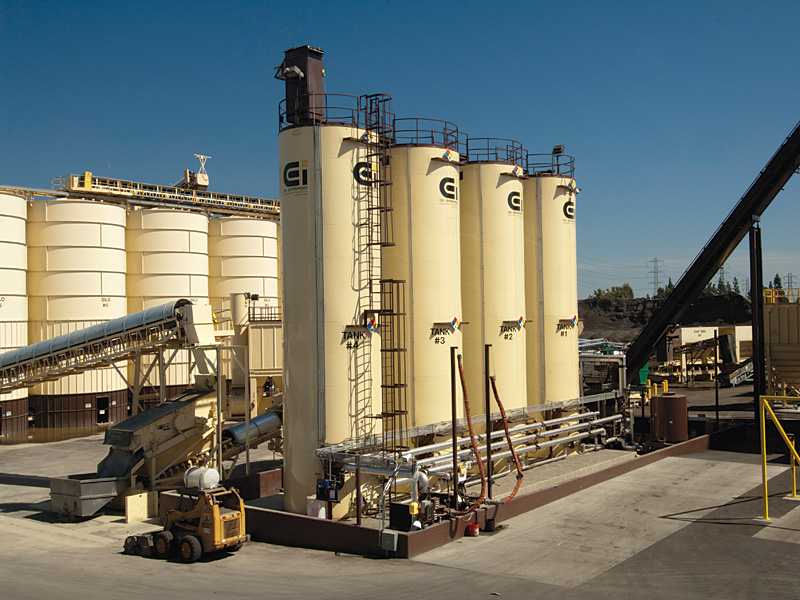 |
The other item that I thought was interesting was that this facility is storing their aggregates in silos instead of in stockpiles. This setup is seen in the background of the photo above and in the photo below:

I've actually never seen a setup like this one and I was extremely excited when I saw it. The grate above is a drive over depository for aggregates. Bottom dump trucks, transporting the plant's aggregate supply from a nearby quarry, drive over this grate and dump their load through the grate (also called a grizzly). The grates stop any over sized materials (if any) and the rest of the rock drops through to the conveyor coming out from underneath it. This conveyor takes the rock to the top of one of the designated aggregate silos where it is deposited for future use at the hot plant. The hot plant can meter the amount of rock from each aggregate silo using their automated controls and no loader is used at all! What I love about this set up is that not only is it going to lead to lower operating costs but also that it is all enclosed. California is quickly moving towards tougher and tougher dust regulations for hot plants and this setup will come close to eliminating dust at their hot plant. In addition, (as if that wasn't enough!) having the rock enclosed in silos with this setup will also help out a ton with storm water requirements since you don't have aggregates which could have chemicals or minerals that can negatively affect runoff sitting in the rain. AND not having wet material because of the rain means lower dryer costs!
As an operations person I'm really excited to see these types of developments but as a quality control person I'm also a little hesitant. One of the reasons that many operations choose not to use aggregate silos is that they have a propensity to segregate material. As I mentioned here when aggregates are dropped from a distance the coarse materials can roll to the outside and the fines stick in the middle. This could lead to coarse materials on the outside edges of your silos and fine materials in the center which can affect your hot mix. There are several ways to combat this though, such as using a gob hopper, so I think that aggregate silos still have a chance at being really great if they are set up and monitored properly. My other curiosity is whether the inherent moisture from the aggregates in the silos will drip down to the bottom of the silo leaving the moisture content of your aggregates inconsistent and possibly affecting your oil content (especially with a drum plant). However, with traditional moistures around 2-3% I'm not sure that it will make that big of a difference in the long run. I just thought I'd let you all in on some of the possible negatives though since there is no such thing as a perfect setup. Overall I think that this facility, belonging to Kelterite, is leading the way to what we're going to be seeing more and more of in the future.
Thursday, September 22, 2011
CT 304 Still Being Updated
Thanks to one of our readers we've found out that the new CT 304 that I spoke about a couple months back (here) is not to be used yet. Soon after the new version was posted on the Caltrans website it was taken down. I looked into it and this is because they are revisiting whether the binder content should be reported as total weight of dry aggregates or as total weight of mix. I'll keep you all updated when the new version is re-posted on the Caltrans website and let you know what they decide. Sorry about the confusion!
Tuesday, September 6, 2011
Cracking from Tree Roots
I was on vacation this past weekend and stumbled upon this patch of road and being the nerd that I am I had to take a photo and share it with you all.

A few weeks ago someone asked me if alligator cracking can be caused by tree roots. The photo above is an example of cracking caused by tree roots. As you can see, the cracks are actually raised up from the ground instead of depressed like you will commonly see with alligator cracking. Maintenance for roads with cracking due to tree roots is a little complicated. In 99% of cases you will need to remove the tree to fix this on-going problem because even if you dig out the roots that are currently under the pavement, the tree will grow new ones and you will be right back where you started.
The tree shown in the picture above is in a state park so the solution to remove it will not work. If you need to keep the tree in place you'll need to find a way to reduce the roots below the pavement. Typically a tree will have 6 to 10 large roots that grow outwards from the tree trunk which provide stability for the tree. It is not advisable to cut these roots because the tree may loose its stability and become a safety hazard. Cutting these major roots will also leave a large portion of the root exposed to the elements which can cause rotting and decay under the soil's surface and may ultimately result in the tree dying. If you find that these roots are the ones that are causing your cracking, you are better off removing the tree. If not, you will dig out the area below your pavement, saw off the roots that are under the pavement area and install a root barrier at the edges of your pavement. The barrier should be placed to a depth of 18-24 inches. If you have good soil depth, the roots will grow down and continue to grow laterally below the barrier but will not have as large of an impact on the pavement you install.
A common mistake that contractors make is by only trenching along the edge of the pavement to cut the roots and install the root barrier. By doing this they leave dead roots under the pavement which will rot and decompose. Once this happens, the pavement can shift and create more cracking. It is better to dig out the entire root system under the pavement.
Another option is to pave with rubberized asphalt. Although the rubberized pavement will still upheave from the roots, it will not crack into sharp cracks as you see above and form rounded mounds instead. This can help aesthetically as well as reduce the tripping hazards from pedestrians and bicyclists.
If you are planning on planting new trees near pavement keep some things in mind. Most tree roots are 2-3 feet below the surface where the good soil is and can be as much as three times the length of the longest branch on the tree. It is recommended that your pavements are 5 feet from any trees to eliminate the chances of the roots damaging it. There are also certain species of trees that will be better suited for planting neared paved areas. Avoid trees with roots that swell and raise near the surface. Also avoid trees with dense canopies that will reduce the amount of sunlight available to the pavement. The lack of sunlight will make it harder for moisture to evaporate which can encourage water damage to your pavement. Some good choices for trees to plant near pavements or sidewalks are hedge maple, cornelian cherry, green ash, chinese juniper, crabapple, scarlet oak, and lacebark elm. A few of the trees that you want to avoid when planting near a paved surface due to large surface roots are red maple, beeches, live oak, pin oak, willow oak, weeping willow, and american elm.
Wednesday, August 31, 2011
Strip Patching
The photo below got me thinking about strip patching and when it can be ineffective. I'm not sure when each of the strip patches below were performed but you can see on the right lane that there are two different patches in the same lane. If these patches were put in at the same time then it seems to me that they should have taken the whole lane out and repaved the lane.

One of the biggest issues that arise from this type of patching is not reaching compaction. Contractors will commonly look at a cracked road surface and try to save money by only digging out and paving the damaged area. This can sometimes be an effective road treatment but only if it is done correctly. The first step to a successful strip patch is to determine if a strip patch is really the right treatment. If you are having problems with both sides of the lane like in the photo above, it is a better idea to repave the entire lane. If you just have one section of the road that needs to be fixed then a strip pave may be the answer. The next step is to cut out the existing pavement. The cut lines should be at least a foot beyond the visible cracking on all sides and should be AT LEAST as wide as your roller or compactor. If your compacting equipment cannot get into the patch area to compact the material then your patch will end up raveling or you could even end up with a cracked surface again. Either of those situations are going to cost you more money and in the end, the money you THOUGHT you saved by skimping on the width of your patch will be spent on yet another patch.
Once you have the pavement dug out you should take a look at the base course. If you had alligator cracking on the pavement before you dug it out you will have to fix up the base course by adding more base rock if necessary and re-compacting. Even if you didn't have alligator cracking you should still check the compaction of the base rock and make sure that everything is compacted, dry, and ready to be paved on before you add your new hot mix.
Next you'll want to make sure that you tack coat all of the vertical faces in your patch. The older pavement will serve as a difficult to adhere your new hot mix to. Tack coat will help the new hot mix stick to the old pavement to reduce the chances of you getting new cracks along the joints of your patch after a month or two as the new mix and old pavement pull apart.
Once you start putting your new hot mix into the patch make sure that you leave the material around 25% higher than the existing pavement. This is so that when your roller compacts the material it will come down to grade and allows a good compaction percentage. If you don't have enough material in the patch to start with, the roller will be able to compact it down to grade but once it hits the height of the existing pavement it will not be able to compact it further due to the roller being hung up on the existing pavement. It will look nice to start with but after a few months the patch will start to ravel. This is the part of patching that is really an art. I've told you that you should have around 25% higher hot mix material than the existing pavement but this will greatly depend on the type of mix you are using on the patch. Just remember that compaction is just as important in a patch as it is when you are paving an entire lane.
Once you've added the new hot mix it is time to rake the material up on top of the patch area and off of the existing pavement. A common mistake that contractors make is by using the bump and fling technique. This is where the raker bumps up the material on the edge and then flings the excess material across the mat so it can be compacted into the middle of the mat. The raker should indeed bump the material up on the edge of the patch but then the material should remain there, on the inside of the crack, until it is compacted. The patch should look like the diagram below right before you start compacting.

Leaving the excess material on the edge of the patch like above allows for the material to be pushed down into the joint between the existing pavement and new patch. This will help with adhesion and compaction on the joint.
The first thing that the roller should do when you're ready to compact is "pinch the edges". The roller drives on the existing pavement on one side of the patch with part of the roller hanging over onto the patch. The compactor drives over the "bumped up" areas of your patch and pushes it down into existing pavement. If you had too much bumped up in this area it's ok. The excess material will be pushed out towards the middle of the mat where you might have flung it anyways, but now you have a well compacted joint instead. The roller then should do the same thing on the other side of the patch and then roll the middle of the patch.
The photo I showed at the beginning of this post is an example of a poor strip patch job. Not only should the contractor have repaved the entire lane but if you look closely you will see that there is a gap between the new patch and the old pavement, probably due to any number of the issues I've discussed today. Patching and maintenance is where the owner can really lose a lot of money or save a lot of money.
If you don't have the money to do it right the first time, where will you get the money to do it over?
Friday, July 22, 2011
Alligator Cracking Continued...
Over the last few days I received the following email in response to my entry Alligator Cracking:
Could the consistency/mixture of the pavement be different? Or maybe the thickness of the pavement is less toward the shoulder than the center. Or flooding or excessive rain at the time it was laid or before the pavement had time to dry, could that cause this? Maybe an underground spring or just ground moisture. Or maybe the ground wasn’t properly prepared before the pavement was laid. Could tree/plant roots cause something like this? How about an earthquake or tremor?
Just a thought.
-Alex
Yes! Almost all of those are potentials for this type of cracking! Typically most of those problems will cause the alligator cracking to appear in various other parts of the pavement as well, not just on the joint.
Mixture variation in the pavement can cause a variety of different issues in the pavement, depending on how the mixture varied. However, alligator cracking is typically a structural problem instead of a material problem. A material issue typically means that the mixture of asphalt binder (oil) and/or rock has problems. When I refer to structural issues it is referring to the "structure" below the mixture that is being laid down. The structure is typically old pavement, base rock, or soil. So when I say that there is a structural problem, that means that there is something wrong with the underlying pavement, base rock, or soil below the new mixture that you're putting down.
The thickness of the pavement is an interesting idea, if this part of the pavement had a thinner layer of pavement than was designed to hold the load, it could easily crack under the pressure.
Rain and moisture at the time of paving could cause this type of cracking but more likely it will cause raveling or shoving instead. The one time that it could definitely be an issue is if the paving crew is paving over aggregate base or soil instead of existing pavement. If the base course is too wet at the time of paving it will tend to move and adjust under the weight of vehicles, sort of like playdough would. This would also happen if there were an underground spring or ground moisture. I would consider this a way of poorly preparing the ground before laying the pavement because it is up to the contractor to assure that his base course is prepped and ready for the asphalt layer. This includes obtaining the correct moisture and compaction of the underlying structure. Another way that the alligator cracking could occur would be if they didn't compact the base rock enough before paving on it.
Roots and earthquakes could absolutely cause these types of cracks as well, however, if it were caused by roots you would tend to see a raised portion in the alligator cracking, where the root is pushing up on the pavement. I hope that answers your questions! Keep them coming!
Tuesday, July 19, 2011
CT 216 Changes-June 2011
Caltrans has released a new version of CT 216: Relative Compaction of Untreated and Treated Soils and Aggregates. The basic test method has remained the same but there were a few additional notes added and a few minor changes that will help to clarify the test method. The changes worth mentioning can be found below:
Happy reading and good luck!
· It no longer specifies miscellaneous equipment in the apparatus section
· In the test method of Laboratory Compacted samples, it now specifies that if there is less than 10% retained on the ¾”, you should divide the passing the ¾” into 5 test specimens of equal weight (within ± 1 g) in the prep stage. Previously it did not specify the amount of specimens at this point in the process and did not specify the tolerance for variance in weight between the samples.
· It now notes that after compaction, when reading the graduated tamper shaft, if the graduation is not level with the top of the mold, you should read the next highest graduation.
· It now notes that some materials may require different moisture content variations besides 2% but that if another increment is used it should be used throughout the test.
· It now notes that excessive moisture on the base plate denotes a failed test point and what to do if this happens.
· Relative compaction is now recorded as the nearest whole number, not to the nearest 0.1% as was previously specified.
· It now specifies that the corrected density on the plot is denoted as a dot with a circle labeled “Adjusted Density”
The June 2011 version of CT 216 can be found on the Caltrans website and at: CT 216 June 2011Happy reading and good luck!
Monday, July 18, 2011
CT 229 Changes-June 2011
Caltrans has issued a new version of CT 229: Method of Test for Durability Index. There were very few changes but below are the ones I thought were worth mentioning:
The June 2011 version of CT 229 can be found on the Caltrans website and at: CT 229-June 2011
Good luck and happy reading!
- The test method has been changed over from metric to US units.
- The specifications for the the lateral reciprocating motion of the coarse aggregate agitator have been changed from 4.75 ± 0.17 Hz to 285 ± 10 cycles per minute. This is due to the change from metric to US units.
- The detailed specifications on the mechanical sand equivalent shaker have been removed and the test method now refers you to the apparatus used in CT 217.
- It no longer specifies the sand equivalent test apparatus.
- You can no longer use tap water in this test, even if it does not affect the test results. The only exception is that you may use tap water during the rinse process.
The June 2011 version of CT 229 can be found on the Caltrans website and at: CT 229-June 2011
Good luck and happy reading!
Friday, July 15, 2011
CT 217 Changes-June 2011
Caltrans has released a new version of CT-217 Method of Test for Sand Equivalent. There were not many changes but the following are the things I thought were worth mentioning. The new June 2011 version can be found on the Caltrans website and at the following link: CT 217-June 2011
· There is now more detailed information for manually-operated sand equivalent shakers. It must be able to oscillate at the rate of 100 complete cycles in 45 ± 5 s with a hand-assisted half stroke length of 5.0 ± 0.2 in.
· You can no longer use tap water in lieu of distilled or deionized water.
· It now specifies the weight of the total starting sample weight to be 1000-1500g of passing #4 materials. Previously there was no weight specified.
· There is now a note on dispute resolution for when manual shakers are used. In dispute, a mechanical shaker will be used.
· It is no longer specified to avoid exposing the plastic cylinders to direct sunlight any more than is necessary
· The Health and Safety section has been rewritten to be less specific and generally puts the responsibility to determine the safety issues and best practices on the user.
Happy reading and good luck!
Wednesday, July 13, 2011
Alligator Cracking
Welcome to post one of disaster roads! The pictures I'll be using for this series were taken by our readers over the fourth of July weekend. If you have a road you are curious about email it to me at toni@qualityincalifornia.com and I'll talk about it in the blog.
This post will focus on alligator cracking based on the photo below:
![]()
For those of you who might not know, alligator cracking is the scaly looking pattern you see on the right side of the photo. Here the cracks have been filled in with a crack sealer which can help to slow the cracking from spreading by keeping out additional moisture. Alligator cracking is one type of fatigue cracking that can happen to a road for a variety of reasons but is most often related to overloading the pavement.
Roads are designed for a variety of variables, two of the biggest are the amount of traffic and the type of traffic. A road in a subdivision may be designed for a lighter load than a Wal-mart loading dock because it is assumed that only small vehicles will be driving there instead of heavy trucks. If a road is designed for a lighter load than is applied to it, the pavement can form a pattern of these types of cracks. Often roads are designed with a lighter load in mind but some vehicles are overlooked. For instance, it seems like a fair assumption that a subdivision will only see small vehicles but the subdivision is still visited by heavy garbage trucks weekly and if there is a bus stop in the area their roads will be overloaded from the bus's weight as well.
However, the road shown above does not seem to be a result of poor pavement design but more poor pavement construction. Take a look at the photo above and notice that the black crack sealant fills in a patch of alligator cracks but then continues up the road in a straight line with a couple more patches of alligator cracks as it goes. The long straight crack is the joint in which one length of pavement was laid down next to another length of pavement. Joints are common places for distresses on roads because if they are not properly installed, the joint can allow for moisture and other debris to wriggle in between the two sections of pavement making the joint a weaker part of the road way. For this very reason, Caltrans and several other government entities specify that joints be lain on lane dividers like the yellow dashed line you see on the left and the white line you see on the white.
The next thing you might have noticed is that the joint is a foot or two to the left of the edge of the lane. The wheels of vehicles travel in this exact area of the lane, placing half of the weight of a vehicle on the joint in this road. The joint is already a weaker section of the road and the additional weight of the vehicle tires overload this section of the road and create a variety of small cracks in the joint that radiate out from the joint line. Over time moisture will accumulate in these cracks. Cold weather will cause the moisture to expand and the cracks will grow until they form a pattern like you see above.
Can you think of any other reasons this road might look like this?
This post will focus on alligator cracking based on the photo below:

For those of you who might not know, alligator cracking is the scaly looking pattern you see on the right side of the photo. Here the cracks have been filled in with a crack sealer which can help to slow the cracking from spreading by keeping out additional moisture. Alligator cracking is one type of fatigue cracking that can happen to a road for a variety of reasons but is most often related to overloading the pavement.
Roads are designed for a variety of variables, two of the biggest are the amount of traffic and the type of traffic. A road in a subdivision may be designed for a lighter load than a Wal-mart loading dock because it is assumed that only small vehicles will be driving there instead of heavy trucks. If a road is designed for a lighter load than is applied to it, the pavement can form a pattern of these types of cracks. Often roads are designed with a lighter load in mind but some vehicles are overlooked. For instance, it seems like a fair assumption that a subdivision will only see small vehicles but the subdivision is still visited by heavy garbage trucks weekly and if there is a bus stop in the area their roads will be overloaded from the bus's weight as well.
However, the road shown above does not seem to be a result of poor pavement design but more poor pavement construction. Take a look at the photo above and notice that the black crack sealant fills in a patch of alligator cracks but then continues up the road in a straight line with a couple more patches of alligator cracks as it goes. The long straight crack is the joint in which one length of pavement was laid down next to another length of pavement. Joints are common places for distresses on roads because if they are not properly installed, the joint can allow for moisture and other debris to wriggle in between the two sections of pavement making the joint a weaker part of the road way. For this very reason, Caltrans and several other government entities specify that joints be lain on lane dividers like the yellow dashed line you see on the left and the white line you see on the white.
The next thing you might have noticed is that the joint is a foot or two to the left of the edge of the lane. The wheels of vehicles travel in this exact area of the lane, placing half of the weight of a vehicle on the joint in this road. The joint is already a weaker section of the road and the additional weight of the vehicle tires overload this section of the road and create a variety of small cracks in the joint that radiate out from the joint line. Over time moisture will accumulate in these cracks. Cold weather will cause the moisture to expand and the cracks will grow until they form a pattern like you see above.
Can you think of any other reasons this road might look like this?
Subscribe to:
Posts (Atom)